Wood Wall Results
Wood Wall results are presented in the Wall Panel Design Spreadsheet and the detail reports.
For additional advice on this topic, please see the RISA Tips & Tricks webpage at risa.com/post/support. Type in Search keywords: Wood Walls.
Wall Results Spreadsheets
Wood Wall Axial Results

Click on image to enlarge it
Wood Wall Panel Axial
|
Column |
Description |
|---|---|
|
Wall Panel |
The Wall Panel column lists the wood wall panels that you have defined. |
|
Region |
The Region column lists the wall panel region that the results are based on. Note: For Perforated or Force Transfer Around Openings design methods, regions are not used. Thus, an N/A will be displayed.
|
|
Stud Size and Spacing |
The Stud Size and Spacing columns show the optimum stud size and spacing chosen for your wall, based on the Design Rules you have defined. |
|
Axial Check |
The Axial Check value is a code check ratio between the member load and the member capacity. |
|
Gov LC |
The Gov LC column adjacent to the Axial Check column shows the governing load combination for the design. |
|
Chord Size |
The Chord Size column shows the optimum chord size chosen for your wall, based on the Design Rules you have defined. Note that the chords are the vertical hold-down members/posts at the both ends of the wall. |
|
Chord Axial Check |
The Chord Axial Check value is a code check ratio between the member load and the member capacity |
|
Gov LC |
The Gov LC column adjacent to the Chord Axial Check column shows the governing load combination for the design. Note:
|
Wood Wall In-Plane Results

Click on image to enlarge it
Wood Wall Panel In Plane
|
Column |
Description |
|---|---|
|
Shear Panel Label |
The Shear Panel Label shows the optimum shear panel arrangement chosen for your wall, based on the Design Rules you have defined. |
|
Region |
The Region gives the region for which the design values are being displayed. Note: The Perforated or Force Transfer Around Openings methods do not consider regions in their design, thus N/A is displayed.
|
|
Shear Check |
The Shear Check value is a code check ratio between the panel shear load and the panel shear capacity. |
|
Shear Force |
The Shear Force column shows the values which governed the design. |
|
Gov LC |
The Gov LC adjacent to the Shear Force column show the load combination which governed the design. |
|
Hold-Down Label |
The Hold-Down Label shows the optimum hold-down product chosen for your wall, based on the Design Rules you have defined. |
|
Chord Strap Label |
The Chord Strap Label shows the optimum strap product chosen for your wall, based on the Design Rules you have defined |
|
Tension Check |
The Tension Check value is a code check ratio between the tension load and the hold-down tensile capacity. This column will only be populated for wood walls at the base level of the structure. The program does not do wall to wall strap design |
|
Tie-Down Force |
The Tie-Down Forceand Gov LC show the maximum value of hold-down/strap which produced the highest strap force. This maximum force could occur on either end of the wall/region. |
|
Gov LC |
The Tie-Down Forceand Gov LC show the load combination which produced the highest strap force. Note:
|
Wood Wall Header Results

Click on image to enlarge it
Wood Wall Panel Header
|
Column |
Description |
|---|---|
| Header Label | The Header Label column shows the label of your header. If there is more than one header in a wall, you can see which is which in the wall panel editor. |
| Design Rule | The Design Rule column shows the rule that is defining the size and material. |
| Size | The Size column shows the size from the Design Rule. |
| Bend UC | The Bend UC column shows the bending code check ratio. This is given for the load combination from the Gov LC column. |
| Shear UC | The Shear UC column shows the shear code check ratio. This is given for the load combination from the Gov LC column. |
| Gov LC |
The Gov LC column shows the load combination that governed the design. The program finds the largest UC value for either bending or shear and reports the associated load combination here. Note:
|
Wood Wall Self Weight
The program calculates the self weight of a wood wall based on the weights of the individual components. Using the material density, the self weight is calculated for the studs, chords, top plates, sill plates, and sheathing. These are all then summed for the total self weight of the wall.
Wood Wall Detail Reports
The detail report gives detailed information about the wall design. The detail reports are specifically molded to the type of design specified. Here we will walk through how to access the different information for each of the types of design: Segmented, Perforated and Force Transfer Around Openings.
- RISAFloor only considers the Segmented design method. If using RISAFloor together with RISA-3D, simply taking your model into RISA-3D will open up the Perforated and Force Transfer Around Openings design methods.
- Many of the values for design checks seen below are not performed in RISAFloor as it is strictly a gravity design program.
Accessing the Detail Reports and the Specific Windows
Once you have a solved model, the detail reports become available. They are accessible in two ways:
- If you have the
- If you are in a graphic view of your model, there is a button that opens the detail report window.
Once the detail report window is open, you see an area at the top of the window.
Detail Report Control Options
| Option | Name | Description |
|---|---|---|
|
|
Prior/Next |
The left and right arrows let you scroll quickly between the different wall panels in your model. |
|
|
Wall Panel Part |
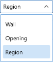
The first drop-down list lets you choose between individual Region and Opening (Lintel) results and a summary of the entire Wall. |
|
|
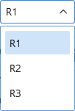
Regions/Headers |
The second drop-down list lets you select between different Regions or Openings within the individual wall panel. “R” represents regions, while “L” represents levels (headers). The is available only when ‘Opening’ or ‘Region’ is chosen in the Wall Panel Part drop-down. |
|
|
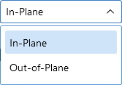
In/Out Plane |
If you have selected a Region, then you have the option of whether to view the in plane or out of plane report. The is available only when ‘Region’ is chosen in the Wall Panel Part drop-down. |
|
The following options can be found at the bottom of the Detail Report window. |
||
|
|
|
Lets you print the Detail Report. |
|
|
Add to Full Report |
Lets you add the current detail report you are viewing to the printed report. View the Printing topic for more information. |

 or
or 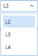


The Wall detail report gives an overall summary of your wall, complete with governing code checks and opening information. The Opening detail report gives information to the header design for the opening as well as detailed information for the Force Transfer Around Openings method. The Region detail report only applies for Segmented walls. Below we have give detailed information on each type of design: Segmented, Perforated and Force Transfer Around Openings.
Segmented Method Results
The Segmented design method uses each of the three detail report windows to give design information.
Wall Window
This window gives an overview of the wall, giving controlling region information and deflection information. Note that this window only gives information on the full-height segments in your wall, as this is the basis of the Segmented method.
Input Echo
This lists information about the wall, similar to the Region report and also gives an image of the wall. The image shows the location of hold-downs/straps, regions and headers.
Design Summary
Detail Report - Design Summary
| Criteria | Description |
|---|---|
| Enveloped Results | The Enveloped Results shows the code checks for all of the controlling elements in the wall and their associated load combinations. |
| Region Information | The Regional Information shows the tabulated results of all of the full-height regions in the wall. |
| Deflection Results | The Deflection Results shows both the calculated NDS deflection (Maximum Region Deflection) the FE deflection for use as a means of comparison. Because the NDS/CSA O86 equations are empirical and take into account many non-elastic considerations such as nail slip, these two values may not be the same. The use of the SSAF helps to make these two values similar. |
| Opening Information | The Opening Information states that header design cannot be completed with the Segmented method. The regions above and below the opening have their shear stiffnesses set to be zero and this causes the header forces to be invalid. |
Opening Window
This window defines the openings in the wall. The segmented wall design method assumes zero stiffness over the opening, therefore, there is no header design for a Segmented wall with openings. Walls specified as a Perforated or FTAO can be analyzed for a header design.
Region Window
This window gives information for your wall on a region by region basis. Note that only full-height regions of the wall panel will have a region detail report. The Segmented method only considers these full height segments in the design of the wall.
The region detail report is split into four portions: input echo, diagrams and design, design details, and cross section detailing. Note that in RISAFloor the detail reports are less detailed because RISAFloor does not consider lateral forces which RISA-3D does.
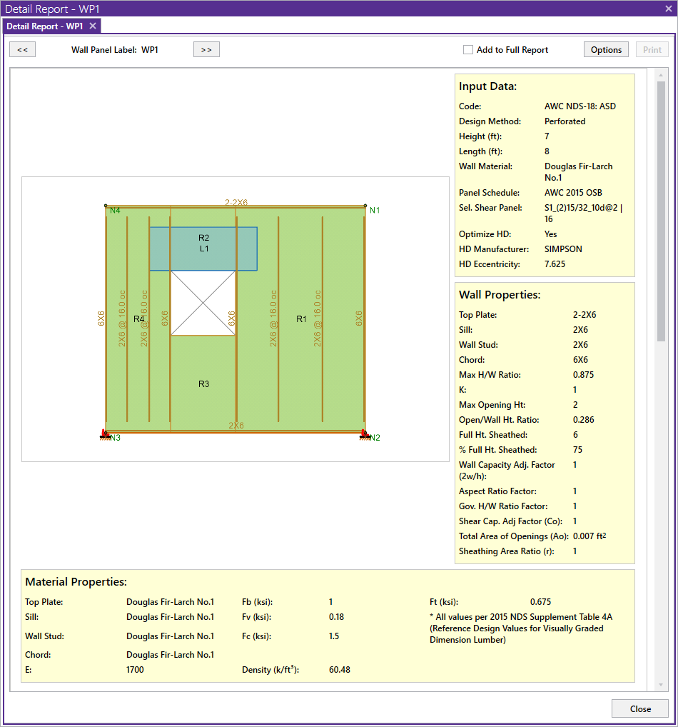
Input Echo
Below is the input echo portion of the detail report.
Criteria section
| Criteria | Description |
|---|---|
|
Code |
Gives the code used to design your wall panel. |
|
Wall Material |
Specifies the wood type assigned to the entire wall |
|
Panel Schedule |
Specifies the sheathing/nailing schedule database used to optimize panel selection (set in Design Rules) |
|
Optimize HD |
Shows whether or not the program needed to optimize the hold-down, or if the user explicitly defined a hold down |
|
HD Manufacturer |
Specifies the manufacturer of chosen hold-down |
|
Strap Manufacturer |
Specifies the manufacturer of chosen strap |
Materials section
| Materials | Description |
|---|---|
|
Wall Studs |
Specifies the wood material type assigned to the wall studs |
|
Stud Size |
Specifies the member size used for the wall studs |
|
Chord Material |
Specifies the wood material type assigned to the chords (vertical members at both ends of the wall) |
|
Chord Size |
Specifies the member size used for the chords (vertical members at both ends of the wall) |
|
Top Plate & Sill |
Specifies the wood material type assigned to the top and sill plates |
|
Top Plate Size |
Specifies the member size used for the top plate |
|
Sill Plate Size |
Specifies the member size used for the sill plate |
Geometry section
| Geometry | Description |
|---|---|
|
Total Height |
This is the height of the wall panel region |
|
Total Length |
This is the length of the wall panel region |
|
Region H/W Ratio |
This is the ratio of wall height to length, using the minimum wall height |
|
Cap. Adj (2w/h) |
This is an aspect ratio reduction factor for the shear panel strength per NDS SDPWS section 4.3.3.4 Exception 1 (2015). This factor applies only for seismic loads, thus it will be 1.0 for wind load combinations per NDS SDPWS section 4.3.4.1 (2005/8). This factor is applied separately for each full-height region in your wall. |
|
Aspect Ratio |
This is an aspect ratio reduction factor for the shear panel strength per NDS SDPWS section 4.3.5.5 (2021) and NDS SDPWS section 4.3.3.4 (2015). This factor applies only for seismic and wind loads on Segmented or FTAO walls. This factor is applied separately for each region in your wall. |
|
Gov. H/W Cap. |
This is the governing (minimum) factor per the Cap. Adj (2w/h) and Aspect Ratios shown above. Only the minimum shall apply per NDS SDPWS section 4.3.3.4 Exception 1. |
|
Wind ASIF |
The code gives a 40% increase in the tables if the lateral load is wind over seismic. For seismic loads this ASIF will be 1.0 (only applicable to NDS design). For LRFD 2021 SDPWS, the code allows a 60% increase in capacity when wind load governs over seismic |
|
Stud Spacing |
This is the optimized stud spacing based on your Design Rules |
|
K |
This is the effective length, K Factor used for stud and chord compression design |
|
HD Eccentricity |
This is the eccentricity of the hold-down connection. This is based on the manufacturer's catalog and measured as the distance from the center of the chord to the hold-down bolt |
Diagrams and Design

Click on image to enlarge it
Envelope Diagrams
These diagrams show the axial forces
- The diagrams are not actually enveloped.
- The Axial diagram shown is the diagram from the governing load combination for Stud design.
- The Shear diagram is the diagram from the governing load combination for Shear Panel design.
- The Moment diagram is the diagram from the governing load combination for Hold-Down design.
Design Summary
This portion gives you the capacity and strength values at the section in the wall where the combined check is maximum, as well as the governing load combination. Much of this information is also reported in the Wood Wall Panel Design spreadsheets.
Design Summary Results
|
Section |
Description |
|---|---|
|
Shear Panel |
This section displays the Shear Panel code check results. The provided capacity of the shear panel is taken from the Shear Capacity column of the panel database. This is the allowable shear value from Table 2306.4.1 from the 2006 IBC (for NDS design) or Table 9.3A, 9.3B, and 9.3C from the CSA O86-14 (for Canadian design). This capacity automatically considers whether the loading is based on wind or seismic loads. The Governing LC explicitly states if the controlling load combination was based on Wind or Seismic. The program does a unity check for all LCs that are being solved, finds the maximum value and reports that information. Note:
|
|
Chord Design |
This section displays the Chord Design code check results. The provided capacities of these members are calculated using the standard provisions for tension/compression members. These members are assumed to be fully braced in the weak axis, and unbraced in the strong axis. For more information on the chord force calculations, see the Wood Wall - Design topic. Note: For chord results, the tension/compression capacity is computed using the reduced cross-sectional properties caused by the hold-down bolt hole.
|
|
Stud Design |
This section displays the Stud Design code check results. The provided capacities of these members are calculated using the standard provisions for tension/compression members. These members are assumed to be fully braced in the weak axis, and unbraced in the strong axis. For more information on the chord force calculations, see the Wood Wall - Design topic. |
|
Hold Down Design |
This section displays the Hold-Down Design code check results. The provided capacity of the hold-down is taken from the Allowable Tension column of the hold-down database. This is information supplied by the manufacturer. Note that we are modifying the Cd value for the hold-down based on taking a ratio of the assumed Cd values from the database and the Cd called for in the Load Combinations spreadsheet. |
|
Chord Straps |
This section displays the Chord Straps results. The provided capacity of the chord strap is taken from the Allowable Tension column of the chord strap database. This is information supplied by the manufacturer. Note that we are modifying the Cd value for the chord strap based on taking a ratio of the assumed Cd values from the database and the Cd called for in the Load Combinations spreadsheet. |
|
This section displays the Deflection results. The deflection listed in the detail report is based on an approximation from the design code. |
NDS Design Deflection
Per the NDS 2021 Special Design Provisions for Wind and Seismic, Equation 4.3-1:
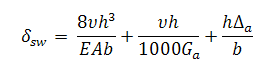
|
Where: |
||
|
b |
= |
Shear wall length, |
|
Δa |
= |
Total vertical elongation of wall anchorage system (including fastener slip, device elongation, rod elongation, etc.) at the induced unit shear in the shear wall, in (This value is taken from the hold down database and scaled per the actual tension force; hence you multiply this value by the holddown ratio given in the output) |
|
E |
= |
Modulus of elasticity of end posts (chords), psi |
|
A |
= |
Area of end post (chord) cross-section, in2 |
|
Ga |
= |
Apparent shear wall shear stiffness from nail slip and panel shear deformation, kips/in. (taken from shear panel database) |
|
h |
= |
Shear wall height, ft |
|
ν |
= |
Induced unit shear, lbs/ft |
|
dsw |
= |
Total shear wall deflection determined by elastic analysis. |
The first term of the above equation determines the Bending Component of the deflection.
The second term of the above equation determines the Shear Component of the deflection.
The third term of the above equation determines the Hold-Down Elongation, which causes additional deflection.
- This is the theoretical deflection of the wall. This may differ from the deflection of the wall as performed by finite element analysis within RISA. Therefore, this deflection value may not coincide with the reported deflection value in the deflections spreadsheets. For information on making the FEM deflections similar to the reported deflections from the NDS calculated deflections, see the Shear Stiffness Adjustment Factor information.
- For Perforated design deflections, the total deflection is to be divided by Coper section 2305.3.8.2.9 of the IBC 2006. Because the unit shear values have already been amplified by Co, the only portion of the deflection that needs to be divided is the hold-down portion.
- The hold-down deflection is reported for the maximum shear LC, which may not result in the largest hold-down component, but typically results in the highest total deflection.
CSA O86 Design Deflection
Per the CSA O86-14 clause 11.7.1.2 (or CSA O86-09 clause 9.7.1.1):
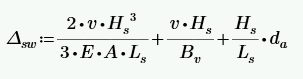
| Where: | ||
|
da |
= |
Total vertical elongation of wall anchorage system (including fastener slip, device elongation, rod elongation, etc.) at the induced unit shear in the shear wall, mm. (This value is taken from the hold down database and scaled per the actual tension force; hence you multiply this value by the hold down ratio given in the output) |
|
E |
= |
Modulus of elasticity of boundary elements (chords), N/mm2 |
|
A |
= |
Area of end post (chord) cross-section, mm2 |
|
Bv |
= |
Shear through-thickness rigidity of the sheathing, N/mm (taken from shear panel database) |
|
Hs |
= |
Shear wall segment height, mm |
|
Ls |
= |
Shear wall segment length, mm |
|
ν |
= |
Induced unit shear, N/mm |
|
Δsw |
= |
Total shear wall deflection determined by elastic analysis. |
The first term of the above equation determines the Bending Component of the deflection.
The second term of the above equation determines the Shear Component of the deflection.
The third term of the above equation determines the Hold-Down Elongation, which causes additional deflection.
- This is the theoretical deflection of the wall. This may differ from the deflection of the wall as performed by finite element analysis within RISA. Therefore, this deflection value may not coincide with the reported deflection value in the deflections spreadsheets. For information on making the FEM deflections similar to the reported deflections from the CSA calculated deflections, see the Shear Stiffness Adjustment Factor information.
- The hold-down deflection is reported for the maximum shear LC, which may not result in the largest hold-down component, but typically results in the highest total deflection.
Design Details

Click on image to enlarge it
Design Details Results
|
Section |
Description |
|---|---|
|
Shear Panel |
The Shear Panel section displays the call-out from the shear panel database. The information below it is the information describing the call-out. Note: There will also be an "Adjusted Shear Capacity" that takes the given shear capacity from the design code and divides it by any appropriate adjustment factors from the Geometry section at the top of the report.
|
|
Hold Down Design |
The Hold-Down section displays the call-out from the hold-down database. The information below it is the information describing the call-out. The "Base Capacity" is the capacity from the manufacturer divided by the assumed Cd value from the database. The "CD factor" that is displayed is the value from the load combinations spreadsheet for the controlling load combination. The actual capacity of the hold-down is the Base Capacity*CD factor. |
|
Chord Straps |
The Chord Strap section displays the call-out from the strap database. The information below it is the information describing the call-out. The "Base Capacity" is the capacity from the manufacturer divided by the assumed Cd value from the database. The "CD factor" that is displayed is the value from the load combinations spreadsheet for the controlling load combination. The actual capacity of the chord strap is the Base Capacity*CD factor. |
The above section of the report echoes the database information for the selected shear panel and hold-down. For more information on these properties refer to Appendix F-Wood Shear Wall Files.
Cross Section Detailing
The last section of the detail report consists of the wall detailing information. This information is provided as a visual confirmation of the wall design. The wall thickness, and stud spacing are shown as dimensions.
Perforated Method Results
Opening Window
This window is similar to the Force Transfer information.
Wall Window
This is where the majority of the information is located for the perforated method.

Click on image to enlarge it
Perforated Method Wall Window
|
Section |
Description |
|---|---|
| Criteria (General) | This section displays some of the important parameters in designing the wall. |
| Geometry |
This section displays dimensions and ratios for the wall panel.
|
| Materials |
This section displays the sizes of the members that are not explicitly talked about in the detail report. Note: The top plate, sill plate and trimmer sizes are used only for the Material Take Off.
|

Click on image to enlarge it
Perforated Method Wall Window
|
Section |
Description |
|---|---|
| Design Details | The Design Details section displays adjustment factors and some other values used to calculate Co. See the Wall Panels topic for more information on the Shear Stiffness Adjustment Factor. See the Wood Wall - Design topic for more information on Co. |
| Deflections | The Deflections section displays the calculated deflection for the three term shear wall equation from the NDS. See above for more information on deflections. |
| Wall Results |
The Wall Results section displays the following information:
|
|
Selected Shear Panel |
The Selected Shear Panel section displays the same shear panel information that was given in the Segmented region report. |
|
Selected Hold-Down |
The Selected Hold-Down section displays the same shear hold down information that was given in the Segmented region report. |
|
Selected Strap |
The Selected Strap section displays the same strap information that was given in the Segmented region report. |
|
Cross Section Detailing |
The Cross Section Detailing section displays a detailed view of the wall. For more information see the Segmented section. |
Force Transfer Method Results
Wall Window
This is the overall wall information and is essentially identical to the Perforated method wall window information. There is some geometry information that is not necessary for FTAO that is omitted.
Opening Window
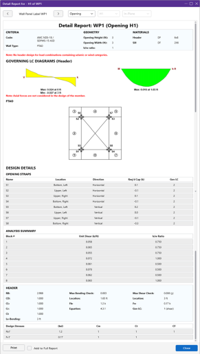
Opening Window
|
Section |
Description |
|---|---|
|
Criteria |
The Criteria section gives the code being used and which design method used. |
|
Geometry |
The Geometry section gives the opening dimensions and the h/w ratio. |
|
Materials |
The Materials section gives dimensions for some of the members in the wall. |
|
Envelope Diagrams |
The Envelope Diagrams give the enveloped shear and moment diagrams for the header beam above the opening |
|
FTAO |
The FTAO graphic shows the design block numbers around the wall panel opening along with the strap numbers. |
Design Details

Click on image to enlarge it
The Design Details section is split into two different tables: ‘Opening Straps’ and ‘Analysis Summary’.
Design Details
|
Section |
Description |
|---|---|
|
Opening Straps |
The Opening Straps information gives the location, direction, force in the strap and the load combination that caused that force. Note:
|
|
Analysis Summary |
The Analysis Summary provides the unit shear and the h/w ratio for each of the blocks. The information below the Analysis Summary section is the code check information for the ‘Header’ member. This is identical to the information given for Segmented Window information. |